


In this example we take a look at the LTR390 UV Light Sensor to a Raspberry Pi 4
Description
This sensor converts light intensity to a digital output signal capable of direct I2C interface.
It provides a linear ALS response over a wide dynamic range, and is well suited to applications under high ambient brightness.
The sensor has a programmable interrupt with hysteresis to response to events and that removes the need to poll the sensor for a reading which improves system efficiency.
This CMOS design and factory-set one time trimming capability ensure minimal sensor-to-sensor variations forease of manufacturability to the end customers.
Features
I2C interface capable of Standard mode @100kHz or Fast mode @400kHz communication; 1.8V logic compatible
Ambient Light / Ultraviolet light(UVS)Technology in one ultra-small 2x2mm Chip LED package
Very low power consumption with sleep mode capability
Operating voltage ranges: 1.7V to 3.6V
Operating temperature ranges: -40 to +85 ºC
Built-in temperature compensation circuit
Programmable interrupt function for ALS , UVS with upper and lower thresholds
RoHS and Halogen free compliant
UVS/ALS Features
- 13 to 20 bits effective resolution
- Wide dynamic range of 1:18,000,000 with linear response
- Close to human eye spectral response
- Automatic rejection for 50Hz/60Hz lighting flicker
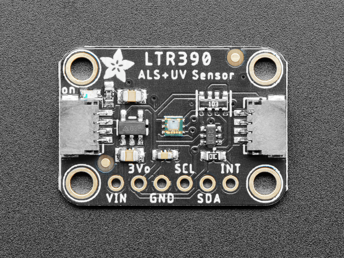
This is the sensor that I bought
Parts Required
Various parts used in this example
The sensor costs about $16 from the link below
Schematic/Connection
I connected the LTR390 to the Raspberry Pi 4 like this
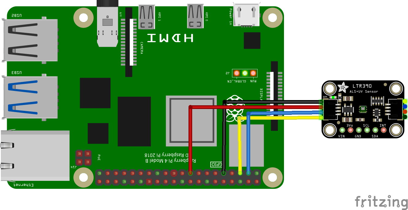
pi and ltr390 layout
Code Example
I used Thonny for development and the library above
[codesyntax lang=”python”]
import time
import math
import smbus

ADDR  = (0X53)

LTR390_MAIN_CTRL = (0x00)  # Main control register
LTR390_MEAS_RATE = (0x04)  # Resolution and data rate
LTR390_GAIN = (0x05)  # ALS and UVS gain range
LTR390_PART_ID = (0x06)  # Part id/revision register
LTR390_MAIN_STATUS = (0x07)  # Main status register
LTR390_ALSDATA = (0x0D)  # ALS data lowest byte, 3 byte
LTR390_UVSDATA = (0x10)  # UVS data lowest byte, 3 byte
LTR390_INT_CFG = (0x19)  # Interrupt configuration
# LTR390_INT_PST = (0x1A)  # Interrupt persistance config
# LTR390_THRESH_UP = (0x21)  # Upper threshold, low byte, 3 byte
# LTR390_THRESH_LOW = (0x24)  # Lower threshold, low byte, 3 byte

#ALS/UVS measurement resolution, Gain setting, measurement rate
RESOLUTION_20BIT_TIME400MS = (0X00)
RESOLUTION_19BIT_TIME200MS = (0X10)
RESOLUTION_18BIT_TIME100MS = (0X20)#default
RESOLUTION_17BIT_TIME50MS  = (0x3)
RESOLUTION_16BIT_TIME25MS  = (0x40)
RESOLUTION_13BIT_TIME12_5MS  = (0x50)
RATE_25MS = (0x0)
RATE_50MS = (0x1)
RATE_100MS = (0x2)# default
RATE_200MS = (0x3)
RATE_500MS = (0x4)
RATE_1000MS = (0x5)
RATE_2000MS = (0x6)

# measurement Gain Range.
GAIN_1  = (0x0)
GAIN_3  = (0x1)# default
GAIN_6 = (0x2)
GAIN_9 = (0x3)
GAIN_18 = (0x4)


class LTR390:
    def __init__(self, address=ADDR):
        self.i2c = smbus.SMBus(1)
        self.address = address

        self.ID = self.Read_Byte(LTR390_PART_ID)
        if(self.ID != 0xB2):
            print("read ID error!,Check the hardware...")
            return

        # self.Write_Byte(LTR390_MAIN_CTRL, 0x02) # MAIN_CTRL=UVS in Active Mode
        self.Write_Byte(LTR390_MEAS_RATE, RESOLUTION_18BIT_TIME100MS | RATE_100MS)# default
        self.Write_Byte(LTR390_GAIN, GAIN_3) # default

    def Read_Byte(self, cmd):
        return self.i2c.read_byte_data(self.address, cmd)

    def Write_Byte(self, cmd, val):
        self.i2c.write_byte_data(self.address ,cmd, val)

    def UVS(self):
        self.Write_Byte(LTR390_INT_CFG, 0x34) # UVS_INT_EN=1, Command=0x34
        self.Write_Byte(LTR390_MAIN_CTRL, 0x0A) #  UVS in Active Mode
        Data1 = self.Read_Byte(LTR390_UVSDATA)
        Data2 = self.Read_Byte(LTR390_UVSDATA + 1)
        Data3 = self.Read_Byte(LTR390_UVSDATA + 2)
        uv =  (Data3<<16)| (Data2<<8) | Data1
        return uv

    def ALS(self):
        self.Write_Byte(LTR390_INT_CFG, 0x14)
        self.Write_Byte(LTR390_MAIN_CTRL, 0x02) #  ALS in Active Mode
        Data1 = self.Read_Byte(LTR390_ALSDATA)
        Data2 = self.Read_Byte(LTR390_ALSDATA + 1)
        Data3 = self.Read_Byte(LTR390_ALSDATA + 2)
        als =  (Data3<<16)| (Data2<<8) | Data1
        return als

    def SetIntVal(self, low, high): # LTR390_THRESH_UP and LTR390_THRESH_LOW
        self.i2c.write_byte_data(self.address, 0x21, high&0xff)
        self.i2c.write_byte_data(self.address, 0x22, (high>>8)&0xff)
        self.i2c.write_byte_data(self.address, 0x23, (high>>16)&0x0f)
        self.i2c.write_byte_data(self.address, 0x24, low&0xff)
        self.i2c.write_byte_data(self.address, 0x25, (low>>8)&0xff)
        self.i2c.write_byte_data(self.address, 0x26, (low>>16)&0x0f)

if __name__ == '__main__':
    sensor = LTR390()
    sensor.SetIntVal(5, 20) # uvs/als set low/high int val
    time.sleep(1)
    try:
        while True:
            val = sensor.UVS()
            # val = sensor.ALS()
            print("UVS: %d"  %val)
            time.sleep(0.5)

    except KeyboardInterrupt:
        exit()
[/codesyntax]
Output
Run this example in Thonny and you will see something like this in the Shell window
I tested this indoors
%Run ltr390.py
UVS: 0
UVS: 0
UVS: 0
UVS: 0
UVS: 0
UVS: 0