


The PCF8574 is an 8 bits I/O port expander that uses the I2C protocol. Using this IC, you can use only the SDA and SCL pins of your Arduino board to control up to 8 digital I/O ports.
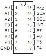
A0,A1,A2 are address pins
P0,P1,P2,P3,P4,P5,P6,P7 are digital I/O ports
SDA,SCL are the I2C pins
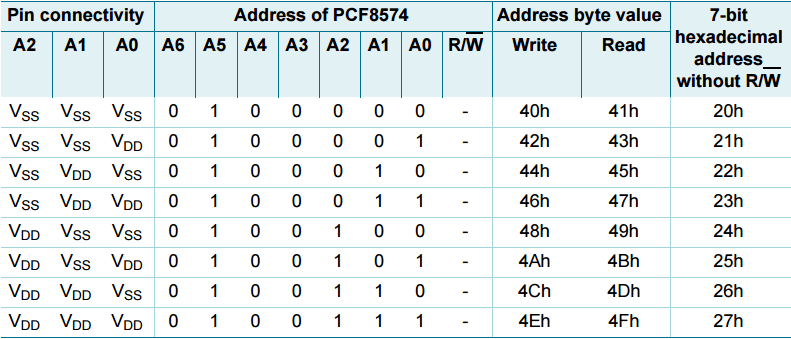
If we set pins A0 to A2 to GND, our device address in binary will be 0x20, thats exactly what I did in my example. To enable read and write there are different values required you can see these in the image below
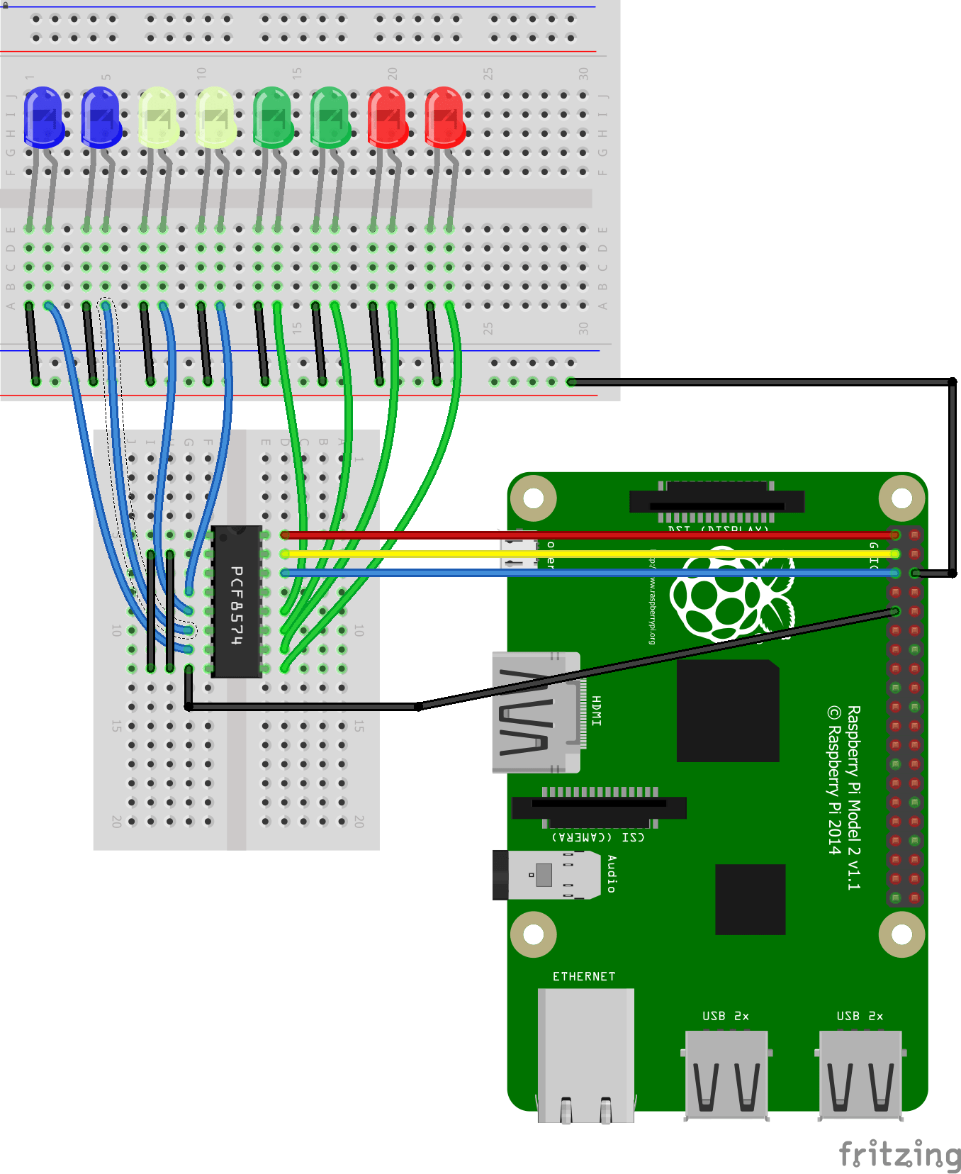
Schematic
Note that the PCF8574 is a current sink device so you do not require any current limiting resistors
I have shown A0, A1 and A2 tied to GND, this is what my test module had selected. In this example I have also shown 8 LEDs connected
Code
This example flashes 4 leds, save it as PCF8574a.py
[codesyntax lang=”python”]
import smbus
import time

LED1 = 0x01
LED2 = 0x02
LED3 = 0x04
LED4 = 0x08
LED5 = 0x10
LED6 = 0x20
LED7 = 0x40
LED8 = 0x80
bus = smbus.SMBus(1)

while True:
	bus.write_byte(0x20, LED1)
	time.sleep(0.5)
	bus.write_byte(0x20, LED2)
	time.sleep(0.5)
	bus.write_byte(0x20, LED3)
	time.sleep(0.5)
	bus.write_byte(0x20, LED4)
	time.sleep(0.5)
[/codesyntax]
Testing
Open a terminal and type in sudo python PCF8574a.py
The led’s will light, I have only shown 4 LED’s in the code but you can see in the example LED5 to LED8 are defined so you can extend it. If you wanted to light multiple LEDs you need to add the values together so lets look at an example where we want LED1, LED2 and LED3 lit at the same time
0x07
Link
PCF8574 Module IO Extension Module