


In a previous example at connecting a mcp23017 to your raspberry pi we used a python script to flash LEDs connected to mcp23017 but there are other options available. In this example we look at a command line tool called i2cset
i2cset is a small helper program to set registers visible through the I2C bus.
usage
i2cset [-y] i2cbus chip-address data-address value [mode] [mask]
i2cset -V
OPTIONS
-V Display the version and exit.
-y Disable interactive mode. By default, i2cset will wait for a confirmation from the user before messing with the I2C bus. When this flag is used, it will perform the operation directly. This is mainly meant to be used in scripts.
There are four required options to i2cset. i2cbus indicates the number of the I2C bus to be scanned. This number should correspond to one of the busses listed by i2cdetect -l. chip-address specifies the address of the chip on that bus, and is an integer between 0x00 and 0x7F. data-address specifies the address on that chip to write to, and is an integer between 0x00 and 0xFF. value is the value to write to that location on the chip.
The mode parameter, if specified, is one of the letters b or w, corresponding to a write size of a single byte or a 16-bit word, respectively. If the mode parameter is omitted, i2cset defaults to byte mode. The value provided must be within range for the specified data type (0x00-0xFF for bytes, 0x0000-0xFFFF for words).
The mask parameter, if specified, describes which bits of value will be actually written to data-address. Bits set to 1 in the mask are taken from value, while bits set to 0 will be read from data-address and thus preserved by the operation.
Here is the memory map for the mcp23017
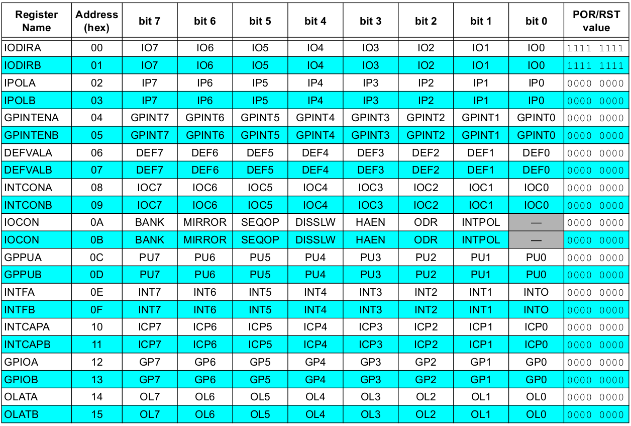
mcp23017
Example
First we configure Port A pins GPA0-7 as outputs. Remember 0x20 is the I2C address of the mcp23017, in the table above you can see that 0x00 is IODIRA and sending 0x00 sets all of the pins to be outputs.
If for example you wanted the first 7 pins to be outputs and pin 8 to be an input then the last value would be 0x80
sudo i2cset -y 1 0x20 0x00 0x00

Then we set GPA0 to a logic high which will enable the LED connected to it
sudo i2cset -y 1 0x20 0x14 0x01

Switch the LED off like this
sudo i2cset -y 1 0x20 0x14 0x00

Here is a screen capture of some more values
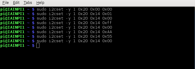
i2cset
If you have 8 LEDs connected to GPA then you will get all LEDs on with 0xFF, 0xAA and 0x55 are a couple of other examples