


MCP4725 is a single channel, 12-bit, voltage output Digital-to-Analog Converter with integrated EEPROM and an I2C Compatible Serial Interface.
Features
12-Bit Resolution
On-Board Non-Volatile Memory (EEPROM)
±0.2 LSB DNL (typ)
External A0 Address Pin
Normal or Power-Down Mode
Fast Settling Time of 6µs (typ)
External Voltage Reference (VDD)
Rail-to-Rail Output
Low Power Consumption
Single-Supply Operation: 2.7V to 5.5V
I2CTM Interface:
Eight Available Addresses
Standard (100 kbps), Fast (400 kbps) andHigh Speed (3.4 Mbps) Modes
Small 6-lead SOT-23 Package
Extended Temperature Range: -40°C to +125°C
As this is a 12 bit DAC converter. What this means is that it will accept up to 4096 possible inputs to provide an analog output, where an output value of zero is zero and an output value of 4095 is full scale.
Full scale is determined by the reference voltage you supply to the VCC pin. Also you can see from above that the supply voltage can be anywhere from 2.7 volts to 5.5 volts. We will use 5v, or as close as what is supplied via the USB in. You may want to measure this voltage for accurate readings, I’ve seen this vary.
This means that to work out the value of the Least Significant Bit (LSB) is as follows:
1 LSB = VCC Voltage / 4096
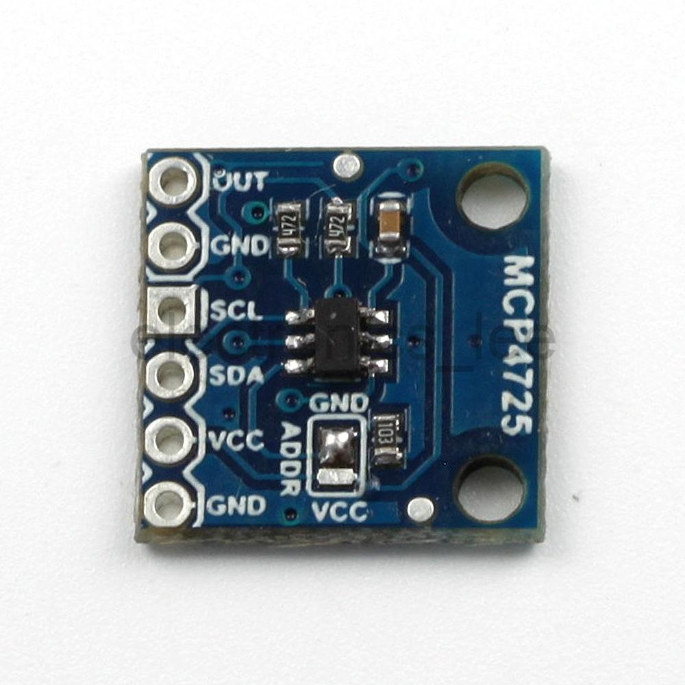
Again the easiest way to interface this to an Arduino is to purchase a module, tehse are available from many sources, here is what my one looked at.
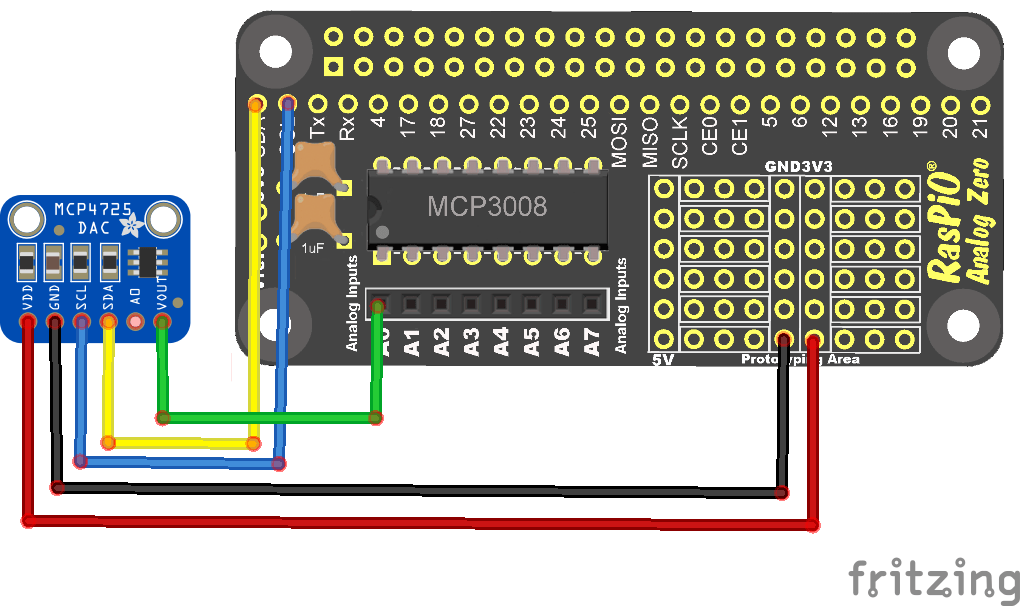
Layout
Just to be different we connect the MCP4725 and rather than using a scope to look at the output we will connect this to a MCP3008 channel 0 and read the value
Code
In this example we will set 2 values and read them in, my module’s I2C address was 0x60 you may need to change this
[codesyntax lang=”python”]
import spidev
import time
import Adafruit_MCP4725
# Create a DAC instance.
#dac = Adafruit_MCP4725.MCP4725()
dac = Adafruit_MCP4725.MCP4725(address=0x60, busnum=1)
spi = spidev.SpiDev()
spi.open(0, 0)
def readadc(adcnum):
# read SPI data from MCP3008 chip, 8 possible adc’s (0 thru 7)
if adcnum > 7 or adcnum < 0:
return -1
r = spi.xfer2([1, 8 + adcnum << 4, 0])
adcout = ((r[1] & 3) << 8) + r[2]
return adcout
# Loop forever alternating through different voltage outputs.
print(‘Press Ctrl-C to quit…’)
while True:
#print(“Setting voltage to 1/2 Vdd!”)
dac.set_voltage(2048) # 2048 = half of 4096
value = readadc(0)
volts = (value * 3.3) / 1024
print (“%4d/1023 => %5.3f” % (value, volts))
time.sleep(2.0)
dac.set_voltage(4096, True)
value = readadc(0)
volts = (value * 3.3) / 1024
print (“%4d/1023 => %5.3f” % (value, volts))
time.sleep(2.0)
[/codesyntax]
Output
This is the output I saw, you can see the half and full Vdd values

Links
MCP4725 I2C DAC Breakout module development board